Solar Camera Progress 1
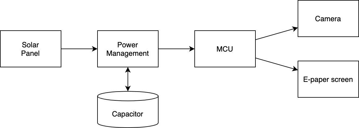
This is basically what my circuit/system be like. Solar energies are harvested by the solar panel and stored in a supercapacitor. They will then power the microcontroller, camera, and screen module. To make the system practical, there are several parameters I need to consider:
- The energy it takes to take one photo and display it on the screen
-> affect how many photo I can take in a roll - The quiescent power consumption of the whole system
-> affect how long it will last when doing nothing - The power the solar panel can capture/produce
-> affect the charging time - The capacity of the super capacitor
-> affect all of the above
Giving up on Raspberry Pi
I was initially planing to build the system with a raspberry pi instead of an arduino. There is a much wider selection in cameras. (I have been dreaming to make a project with the new High Quality Camera for a long time.) And it also perform way better than most microcontrollers so I can run more complex image processing code or even computer vision model.
However, the power consumption of raspberry pi is just so high. I measured the current of my Pi Zero which is already the smaller version, and it still took about 100mA when it is basically doing nothing. It makes sense since they are not designed to be super power efficient but for better performance. So for this project, I have to switch to MCUs.
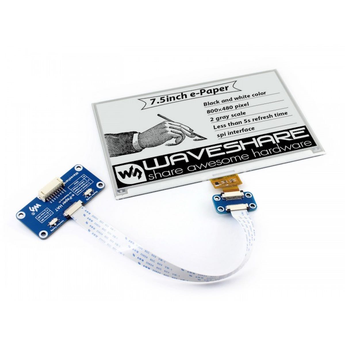
Screen
This is the part that I decided first. A 800x480 7.5 inch E-ink display seems like a good fit. Some important power specifications are:
- Full refresh time: 5s
- Refresh power: 38mW(typ.)
- Standby power: <0.017mW
Microcontroller / Dev Board
The basic Arduino Uno board is power-efficient enough for this project, but its RAM is too small to drive the 800x480 pixels. Here are some mcu that I found can be fit in this project. Besides power consumption, code library support is also an important factor since I don’t want to waste time rewriting protocols. These chips have good power efficiency and also well-supported community.
It need to be noted that the ESP32 also support WiFi & Bluetooth.
| Chip | Power (active) | Power (sleep) |
|---|---|---|
| SAMD21 | 10mW | 10uW |
| RP2040 | 200mW | 4mW |
| ESP32 | 500mW | 30uW |
Another thing that need to consider is the voltage regulator. A simple LM1117 that most board have is not good for power efficiency. Having a 5mA quiescent current and a 1.2V drop voltage could be a lot of waste. However, this can be easily fixed by adding a better LDO like MCP1700 and power the microcontroller with direct regulated 3.3V.
An IoT board like the FireBeetle ESP32 by DFROBOT could be a perfect fit for this project. I also like the new Raspberry Pi Pico cause there is already community support for e-paper and there is a very power-efficient camera module built specifically for this board (which I explain in the following paragraph). A SAMD21 board like the Seeeduino XIAO is also a good idea cause it almost cost nothing in energy.
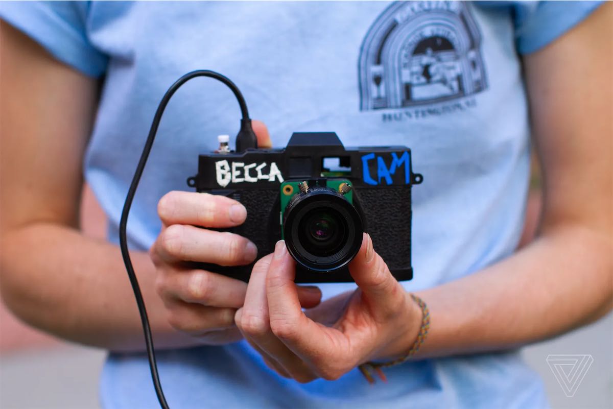
Camera
Cameras are pretty heavy in power consumption and also more sophisticated to code. One easy solution is the ESP32-Cam. It’s an ESP32 dev board with a builtin camera (usually an OV2640 or OV7670).
| Name | Quality | Power (active) | Power (sleep) |
|---|---|---|---|
| OV2640 | 1600x1200 | 125mW | 2mW |
| OV7670 | 640x480 | 60mW | < 60uW |
| HM0360 | 640×480 Monochrome | < 19.6mW | < 140uW |
| HM01B0 | 320×320 Monochrome | < 1.1mW | < 200uW |
The last two cameras are built specificlly for the new Raspberry Pi Pico. They are just been released and haven’t started shipping yet. The low resolution and monochrome don’t appear to be a problem in this project since I’m gonna display the image on a low res b&w e-paper.
- Arducam HM0360 VGA SPI Camera Module for Raspberry Pi Pico
- Arducam HM01B0 QVGA SPI Camera Module for Raspberry Pi Pico
I wish I can get those as soon as possible and adapt the code to seeeduino Xiao. So the the final product can be super small and super power-efficient, too.